Mouyen F, Benz C, Sonnabend E, Lodter JP. Presentation and physical evaluation of RadioVisioGraphy. Oral Surg Oral Med Oral Pathol. 1989; 68:238-242
Güniz Akdeniz B, Gröndahl H-G, Kose T. Effect of delayed scanning of storage phosphor plates. Oral Surg Oral Med Oral Pathol Oral Radiol Endo. 2005; 99:603-607
White SC, Pharoah MJ., 6th edn. Oxford: Mosby Elsevier; 2009
Haak R, Wicht MJ, Nowak G, Hellmich M. Influence of displayed image size on radiographic detection of approximal caries. Dentomaxillofac Radiol. 2003; 32:242-246
Haak R, Wicht MJ, Hellmich M, Nowal G, Noack MJ. Influence of room lighting on grey-scale perception with a CRT and a TFT monitor display. Dentomaxillofac Radiol. 2002; 31:193-197
Petersson A, Warfvinge G, Nilsson M. Effects of ambient light and monitor brightness and contrast settings on the detection of approximal caries in digital radiographs; an in vitro study. Dentomaxillofac Radiol. 2008; 37:380-384
Dental radiographic imaging is slowly transferring to digital format. The decision to invest in this new technology should be based on a good understanding of the different types of digital imaging available within the dental field. This article outlines its use in general dental practice, highlighting the pros and cons of the various systems both for intra-oral and extra-oral radiography.
Clinical Relevance: An understanding of the mechanisms of digital imaging and their associated potential problems are required by any clinician moving to film-less imaging.
Article
Since the early 1990s there has been a trend to move from film-based to digital radiography in medical radiology departments in hospitals throughout the NHS, such that it is now rare to find radiographic films in use. One drive for this revolution has been the huge economical gain that can be achieved by obviating the significant physical storage space required for the vast numbers of films generated. This move to digital imaging in the UK was made possible by funding from the Department of Health and advancements in technology allowing images to be electronically stored in a secure manner, for example using a Picture Archiving and Communication System (PACS), which has become the mainstay of hospital radiology electronic storage. Subsequently, a system was been developed that now involves nearly all NHS Trusts in England allowing relatively simple sharing of radiographic images between clinicians in different parts of the country, thus allowing expert opinion to be easily sought, and avoiding the need for repeat radiography.1
Conversion to digital imaging within dentistry in the UK has been much slower in dental hospitals, general dental practice, and in community-based services. It has been estimated that approximately half of dental practices in England have converted to digital imaging systems, whereas other European countries have seen a much faster change. This slow uptake is surprising given that the first digital imaging systems were designed for dental intra-oral images.
This paper aims to review digital dental radiology in practical terms to explain the equipment, its use, and differences in comparison to film-based dental radiography.
Image acquisition of dental radiographs requires an X-ray generating machine and some form of image receptor. The mode of X-ray production has not changed with the introduction of digital radiography and thus dental X-ray sets for intra-oral radiographs do not require replacement when a practice moves to a digital radiography system, provided the X-ray machine is able to deliver exposure times that are short enough for digital intra-oral imaging.
All dental X-ray machines in the UK should be operating between 60 and 70 kilovolts (kV), rectified with either AC (alternating current) or DC (direct current) voltages, contain inherent aluminium filtration and incorporate 20cm focus-to-skin distance spacer cones with rectangular collimation. In addition, beam aiming devices should be used for paralleling techniques to ensure geometric accuracy.2 The main difference with digital radiography is the mode of image capture. This paper aims to give an overview of the two different technologies available for digital imaging in dentistry and then discusses in more detail their application to intra-oral and extra-oral radiography.
There are two modes of digital imaging currently available:
Direct digital radiography (DR) utilizing solid-state sensors; and
Both of these systems capture a digital radiographic image as a two-dimensional representation of the three-dimensional patient, in common with traditional film-based radiography, but the image is constructed of tiny black, white and grey square picture elements called pixels, rather than the variable accumulation of the silver grains on radiographic film, that leads to a variation in optical density. A typical digital image is constructed using 256 shades of grey.
Both forms of dental digital imaging receptors capture a good diagnostic image with a very short exposure time, thus allowing a potentially lower patient dose. Traditional radiographic films of different speeds (D, E or F) require optimal exposure factors to produce a diagnostically satisfactory image. The same is not true of both forms of digital radiography where wider exposure latitude exists, particularly with phosphor plates (Figure 1). This could be seen as an advantage in that it provides a wider range of exposure factors that will always produce a good radiograph; however, it is still imperative to ensure that the lowest possible exposure time is used to ensure compliance with the fundamental radiation protection principle of ALARP (As Low As Reasonably Practicable). Guidance from a medical physicist is therefore required to ensure exposure settings are adjusted appropriately when moving to a digital system.
Figure 1. Variation in brightness and contrast between radiographic film and phosphor plates with varying exposure time. Exposures of 0.04, 0.8, 0.16 and 0.32 s were used to capture images using size 2 Kodak Insight Film (F-speed) (a-d) and a Digora Optime Phosphor plate (e-h) in a phantom head. A Sirona Heliodent dental intra-oral X-ray tube was used, operating at 60 kV DC and 7 mA. Note the considerable variation in image contrast of the film compared to the similar image displayed using the phosphor plate.
Direct digital radiography (DR)
Direct digital radiography was introduced to the medical imaging market from its origins in dental radiography, with the production of the RadioVisioGraphy (RVG) imaging system from Trophy in 1987.3 Since this time many new generations of solid-state imaging sensors have been developed for use both intra-orally and extra-orally. They are constructed from charge coupled devices (CCD) or complementary metal oxide semiconductors (CMOS) arranged in an array.
Within the plastic casing of the sensor the CCD/CMOS array is overlaid with a scintillation layer. The radiographic image is created by X-ray photons striking the scintillation layer which converts the X-ray photon energy into visible light. The light produced in a given area of the scintillation layer interacts with the CCD/CMOS locally creating a charge that is concentrated on an electrode; this charge in the electrode forms the pixel (picture element) of the final image. The image is created as each row of electrodes within the solid state sensor is read and the information transferred down a fibre optic cable as an analogue signal. This is passed to the computer where a digital convertor changes it into a digital signal. (One manufacturer markets a wireless intra-oral version, obviating potential clinical problems encountered when positioning an intra-oral sensor in the mouth with an attached cable.) The digital image is finally constructed on the viewing station. The amount of radiation each pixel within the sensor receives will determine the grey-scale depicted in the final image for each pixel; the more radiation that reaches the sensor the darker the image. In a typical 8 bit imaging system there are generally 256 shades of grey. This grey-scale image results in the black/grey/white digital radiograph visualized on the computer monitor.
There are two significant advantages of direct digital radiography:
The images are produced instantaneously; and
The sensor is ready for immediate re-use.
Computed radiography (CR)
Computed radiography utilizes photostimulable phosphor plates, constructed of a polyester base sheet coated with an emulsion containing europium-activated barium halide phosphors. Activation of these phosphors by X-ray photons excites electrons to a higher energy level which are stored there until the plate is read or processed. The processing requires a plate reader (Figure 2) that utilizes a laser beam which sequentially scans the phosphor plate from side to side, and in so doing releases the stored energy as fluorescent light. This light is captured, intensified in a photo-multiplier tube and the intensity of the light converted to a digital signal specific to the given pixel area of the phosphor plate. Thus the energy of the X-ray photons striking any given point on the phosphor plate is converted to a shade in the grey-scale. Once again, the more radiation that reaches the plate the blacker the image and once again 256 shades of grey are available which results in the black/grey/white radiographic image visualized on the computer monitor. Although the image is not created instantaneously, the time taken for an intra-oral plate to be read and converted to an image is of an order of seconds and much faster than film-based chemical processing.
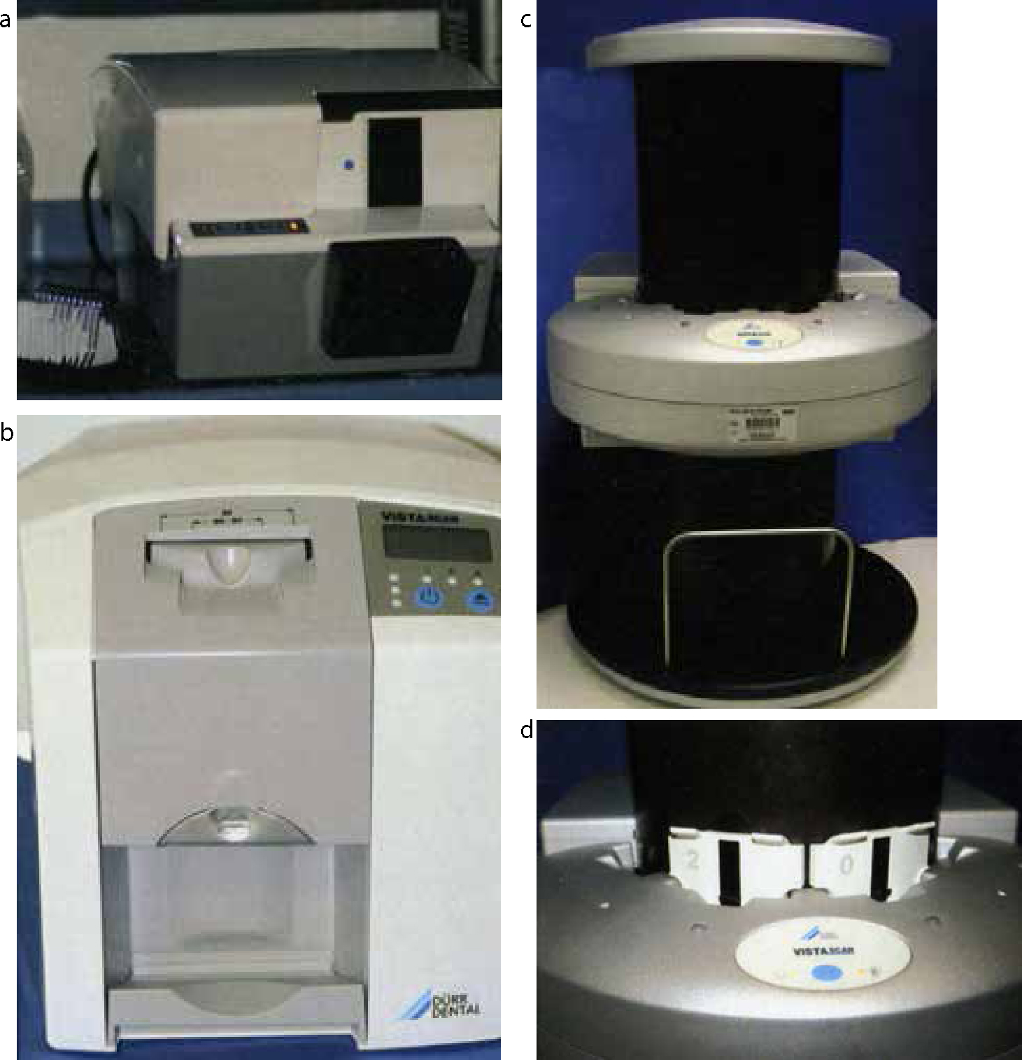
Figure 2. Phosphor plate readers. (a) Digora Optime Classic reader that accepts size 0–3 phosphor plates. (b) Durr Vistascan Mini Intra-oral reader that accepts size 0–4 phosphor plates. (c, d) Durr Vistascan Combi Intra-and Extra-oral reader that accepts all intra-oral plates, as well as panoramic and cephalometric plates.
When the laser reader scans the plate not all of the energy that was stored on the plate is released. It therefore needs to be cleared to erase the latent image fully before it can be re-used. This is achieved by a white light scan of the plate. Early systems required the operator to perform this step manually by exposing the plates to bright light but it is now performed automatically by most contemporary phosphor plate readers.
Various models of reader are commercially available (Figure 2) with options to allow occlusal-sized plates to be scanned in addition to smaller intra-oral and extra-oral plates, with some machines providing multi-plate scanning for high throughput reading if required.
The characteristic of phosphor plates that requires them to be cleared by light has both advantages and disadvantages. Following reading, a plate can be handled in ambient light conditions during preparation for its next use, without the need for a dark room. However, following a diagnostic exposure, care must be taken while unwrapping a plate prior to reading, as exposure to bright light must be avoided as this would lead to degradation of the latent image, and thus loss, or reduction, of diagnostic information. This is readily observed in radiographs where part of the irradiated but unread plate is exposed to bright sunlight. The affected part of the final image will be very pale, with consequent reduction or possibly even loss of the diagnostic value of the image (Figure 3a). If phosphor plates are kept wrapped (ie in the dark) the latent image can be preserved for over 24 hours prior to processing/reading, but ideally they should be read within 10 minutes of exposure before any diagnostic information starts to be lost.4
Figure 3. Common faults seen with phosphor plates and CCD. (a) Radiograph captured with a phosphor plate that was exposed to bright light prior to reading, resulting in partial clearing of the plate and hence brightness in the region of LL8. (b) Radiograph captured with a phosphor plate that is damaged by multiple scratches. (c) Radiograph captured with a phosphor plate that was reversed; the round circular artifact overlying LR6 is the magnet on the back of the plate. Note that an image has been captured, which would not be the case if a film was reversed during exposure, however, the image is of low quality. (d) Radiograph captured with a CCD, but due to over-exposure the image is very dark as a result of ‘blooming’.
During periods of inactivity the highly sensitive phosphors will be energized by background radiation and it is therefore good practise to clear the plates prior to use at the start of each week.
Intra-oral radiography
Image receptor sizes
Most direct digital radiography (DR) commercial systems utilize only two sizes of intra-oral solid-state sensors for use in bitewing and periapical radiography, namely an adult (up to 34 x 26 mm) and a child (up to 30 x 20 mm) size, and are therefore more limited than film-based or computer radiography (CR) intra-oral systems (Figure 4). To date an occlusal sized solid-state sensor (57 x 76 mm) is not available. CR systems generally offer phosphor plates of very similar sizes to the regular dental film sizes. They are wrapped in protective card and a light-tight waterproof barrier envelope for clinical use, to protect the plate from damage, such as scratches, and to maintain dark conditions, thus avoiding erasure of the latent image. Once packaged the intra-oral phosphor plates have a very similar appearance to dental film (Figure 4).
Figure 4. Intra-oral phosphor plates and Intra-oral CCD sensor. (a) Size 4 Digora PCT occlusal imaging plate showing the front receptive surface (blue) and the black back with magnetic circle. (b) Size 2 (31 x 40 mm), size 1 (24 x 40 mm) and size 0 (22 x 31 mm) Digora Optime phosphor plates and a CCD imaging sensor showing the receptive surfaces. (c) The same CCD imaging sensor view from the side to indicate the depth of the sensor and cable attachment. (d) Size 2 Digora Optime phosphor plate with its card cover and plastic barrier bag. (e) Size 4 phosphor plate (black arrowhead), with card cover (black arrow), bite shield (white arrowhead) and plastic barrier wrap (white arrow) showing their assembly.
A further consideration is the overall size of the captured image relative to the size of the image receptor. The size of the CCD or CMOS array that captures the X-ray photons in a DR intra-oral sensor, and therefore the image, is significantly smaller than the size of the plastic housing, whereas with phosphor plates and conventional film the size of the package closely matches the image capture area.
Infection control considerations
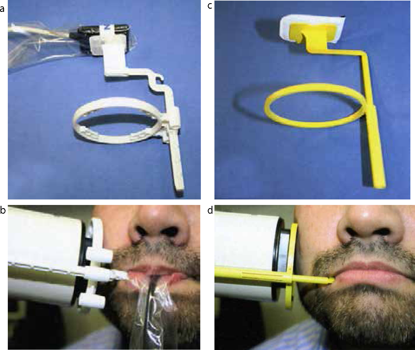
Solid-state sensors are made of rigid plastic and in most DR systems the intra-oral sensor is linked to the computer by a fibre-optic cable (Figures 4 and 5). As a result, specific infection control measures must be employed since the solid-state sensors and fibre-optic cable cannot be autoclaved but may be disinfected, depending on the manufacturer's instructions. In practice, it is usual to use a plastic barrier wrap (covering the sensor and cable) that must be changed between patients (Figure 5). Phosphor plates are barrier-wrapped as these plates cannot be autoclaved or chemically disinfected (Figure 4), although some modern systems now offer an ultraviolet disinfection.
Figure 5. Intra-oral CCD and phosphor plate holders and beam aiming devices. (a) CCD within its barrier wrap held in a Rinn disposable Uni-Grip 360 Universal sensor horizontal bitewing holder, that incorporates a beam-aiming device. (b) A CCD sensor in the same Rinn holder in clinical use. (c) A wrapped size 2 phosphor plate held in a Kwik-bite holder for horizontal bitewings. (d) The same phosphor plate and holder with beam-aiming device in clinical use.
Clinical considerations
The rigid plastic housing of the DR solid-state sensors can make them unwieldy and difficult to position precisely within the mouth to ensure the field of interest is imaged (Figure 4). Clinical use can be further complicated by the fibre-optic cable which needs to be protected from physical damage. Taking a conventional bitewing radiograph with the teeth in occlusion is nearly impossible. The relatively small size of imaging area requires the operator to place the sensor very accurately (Figure 6). As in film-based dental radiography, beam-aiming devices are advised to aid geometrically accurate radiography and reduce patient dose. Specialized holders for solid-state sensors with beam-aiming devices are available which are not interchangeable with conventional film packet holders, given the variation in size and design (Figure 5).
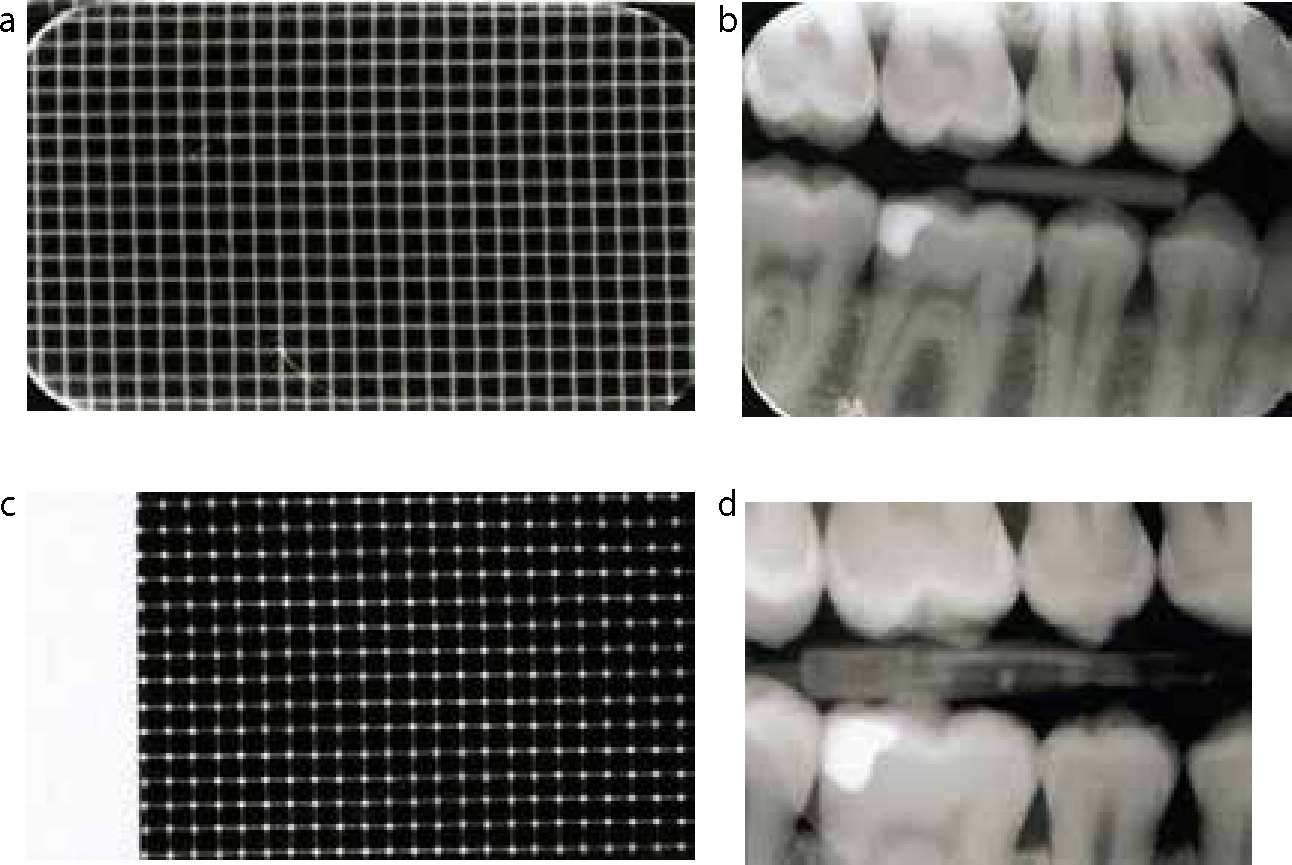
Figure 6. Comparison of the sensor area of a phosphor plate and CCD. (a) A metal grid imaged on a size 1 phosphor plate (29 x 18 boxes). (b) Right horizontal bitewing captured using a size 2 PSP (c) The same grid as in A imaged on an child CCD (24 x 15 boxes) indicating the smaller active sensor size. (d) Right horizontal bitewing of the same patient shown in (b) captured using an adult CCD; note the smaller area imaged. The linear artifact overlying LR7 is a cracked scintillator within the sensor.
On the other hand, once packaged in their barrier envelopes, intra-oral phosphor plates have a very similar appearance to dental film packets (Figure 4). The advantages of this includes the ability to use the same film holders, with beam aiming devices and radiographic techniques that do not need to be adapted (Figure 5), except for optimal adjustment of exposure factors.
Both types of digital image receptors should be handled carefully. While solid-state sensors are fairly robust, the scintillation screen is at risk of fracture if dropped. This would result in a line representing the crack on all subsequent radiographs taken using the sensor (Figure 6d). This would obviously require replacement of the sensor. The phosphor layer of the CR plate is very easily scratched and permanently damaged. It is therefore also good practise that plates are checked regularly for damage including dirt on the plates and scratches (Figure 3b).
Exposure considerations
While post image manipulation software allows for some correction of exposure variation, this can be exceeded if, for example, a solid-state CCD sensor is over-exposed. This results in blooming (Figure 3d) which happens because the X-ray photon energy received by a given area of the scintillation layer results in such high levels of light production that the energy exceeds the capacity for the corresponding component of the CCD and therefore spills over into adjacent areas. The result is inappropriate darkness over areas of the image and therefore loss of image detail which cannot be corrected by subsequent digital image adjustment. This phenomenon is not observed in CMOS detectors.
As already stated, phosphor plates have a very wide latitude and are therefore capable of creating a diagnostically acceptable image even if over-exposed, hence the imperative to ensure that the lowest possible exposure time is used to ensure compliance with the ALARP principle. The phosphor crystals are so receptive that the plates can be exposed back to front and still produce an acceptable, but reversed, image (Figure 3c).
A comparison of intra-oral film, phosphor plates and solid-state sensors is shown in Table 1.
Film
Phosphor Plates
CCD/CMOS
60–70 kV dental X-ray set
60–70 kV dental X-ray set
60–70 kV dental X-ray set
Film supplied pre-packaged
Plates must be wrapped prior to use
Sensor barrier wrapped prior to use
Requires chemical processing
Requires plate reader attached to a computer
Sensor linked to a computer, no additional processor required
Processing requires dark room or automatic processor and safe light conditions
Image readout can be performed in ambient light, but not bright light
No processing required – automatic procedure
Established techniques for intra-oral radiography using film holders and beam aiming devices
Identical techniques to film-based intra-oral radiography using a film holder and beam aiming device
Modification of radiographic techniques to accommodate the cable and sensor, specialized sensor holders must be used
Several intra-oral film sizes available
Plate sizes match the available film size
Only 1 or 2 sizes of sensor usually available
Small and thin films are tolerated in the mouth
Same as film
Bulky sensors covered by a protective sleeve must be placed in the mouth
Film can deteriorate prior to use if not stored correctlyRequires good processing to produce a good radiograph
Plates will deteriorate over time, requiring replacement, and poor handling can lead to scratches and dirt on the surface leading to poor image quality
Sensors may be broken and replacement is at a significantly higher cost than of phosphor plates
Extra-oral radiography
Extra-oral direct digital radiography
Dental panoramic DR machines are purchased as a single integrated unit with an inbuilt solid-state sensor (Figure 7). Combined panoramic/cephalostat digital equipment is also available. The solid-state image receptors in these extra-oral units are different from those used in intra-oral radiography. They are composed of a narrow linear CCD/CMOS array aligned to a narrow X-ray beam. The image receptor and the X-ray source move during the exposure as the patient is scanned. This design is therefore readily adaptable for use in rotational dental panoramic radiography which conventionally involves equipment movement. The image is created increment by increment as the beam rotates around the patient with the sensor constantly exposed-read-exposed-read during the exposure. The panoramic image is therefore created in real-time on the computer monitor as the patient is being imaged.
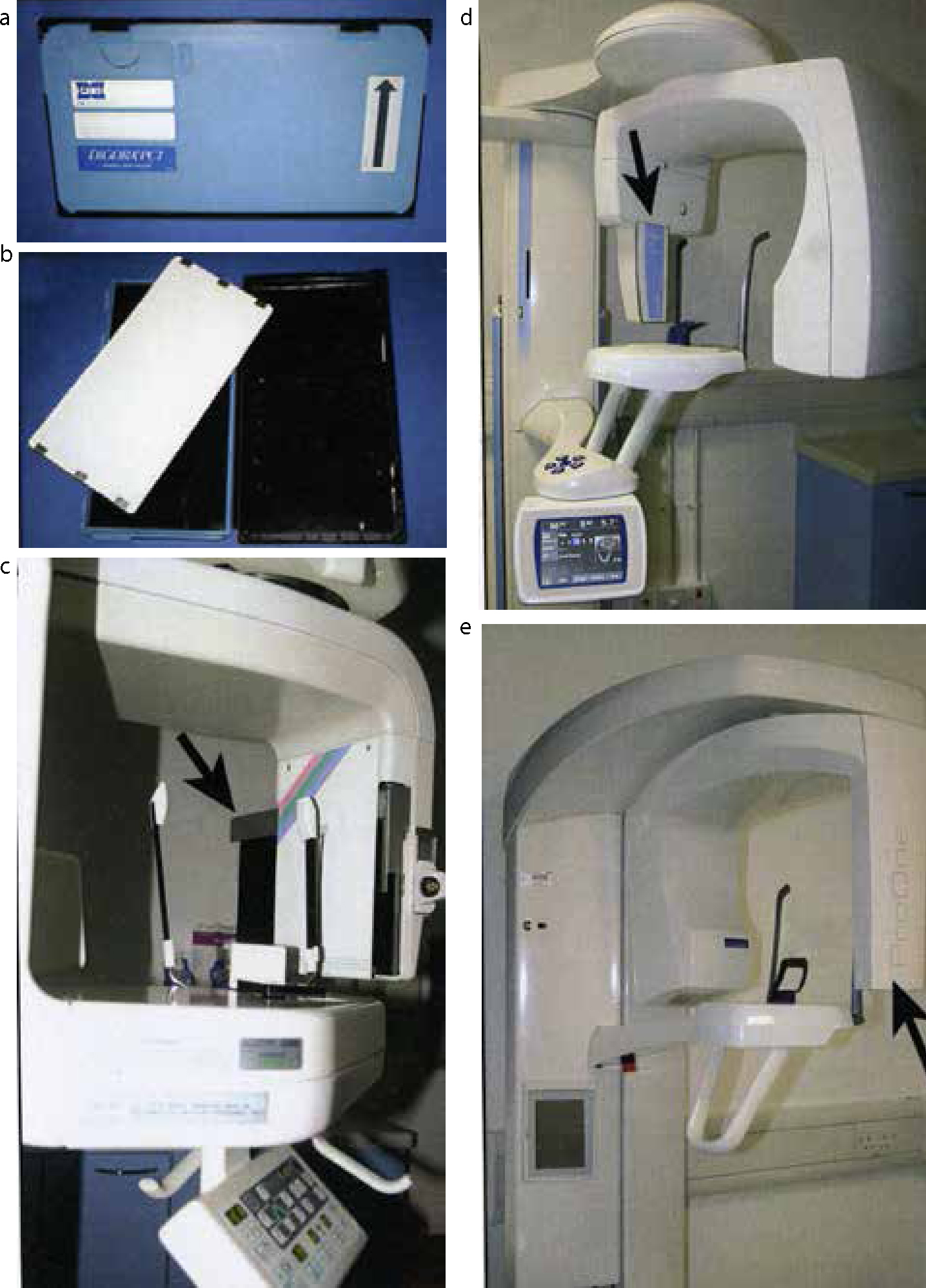
Figure 7. Extra-oral digital radiography equipment. (a) A Digora PCT panoramic phosphor plate cassette. (b) The same cassette with the phosphor plate, 30 x 15 cm (note no intensifying screen present) (c) Planmeca Proline CC film/phosphor plate panoramic machine; arrow indicates the cassette carriage. (d) Planmeca Promax Direct digital panoramic machine; arrow indicates the sensor. (e) Planmeca Pro One Direct Digital panoramic machine; arrow indicates the sensor.
Direct digital cephalometric radiographs are also typically created using a narrow fanned X-ray beam and one, or sometimes two, vertically stacked narrow linear CCD/CMOS sensors. The image receptor and the X-ray source again move, usually anterior to posterior, during the exposure as the patient is scanned. This scanning time takes several seconds and is considerably longer than with conventional film-captured cephalographic imaging and may result in movement artefacts. If two stacked sensors are used, the two images created will have to be stitched during image processing which may create visible line artefacts on the final image.
It is possible to purchase digital cephalometric imaging systems that utilize a single flat panel imaging detector which functions in the same way as a large intra-oral sensor. No equipment movement is involved and hence less chance of movement artefact.
Extra-oral computed radiography
To switch to CR dental panoramic and cephalometric imaging does not require a new machine as the cassettes that house conventional panoramic and cephalometric-sized phosphor plates are identical to those used for panoramic and cephalometric film (Figure 7). The critical difference between the cassettes for CR and those for film-based imaging is that CR cassettes do not contain fluorescent phosphor intensifying screens (Figure 7). The cassettes in film-based panoramic/cephalometric imaging contain a compatible film/screen combination to produce a good quality low dose image. The intensifying screens emit light on activation by incident X-ray photons which in turn affects the light sensitive film emulsion. The effect of such light would be to erase any latent image forming on a CR phosphor plate! The role of the cassette in CR panoramic imaging is simply as a vehicle to protect the phosphor plate, as well as to maintain dark conditions thus preserving the latent image until processed. Hospital X-ray departments often use large capacity automated phosphor plate readers which require minimal interaction with the plate (Figure 8); however, these are unlikely to be required in a dental practice. Although CR panoramic/cephalometric radiography does not require investment in a new X-ray machine, it does require the purchase of a reader with the capacity to process these larger plates.
Figure 8.
(a) Agfa CR85-X Medical grade automated phosphor plate reader. (b) Agfa Drystar 4500M Diagnostic thermal imaging printer for high quality images.
A comparison of extra-oral film, phosphor plate and solid state sensors is shown in Table 2.
Film
Phosphor Plates
CCD/CMOS
Panoramic machine incorporating a cassette carriage
Same machine can be used with film
Specialized machine must be purchased
Cassette must contain intensifying screens preferably of rare earth type
Intensifying screens not required within the cassettes as the light produced will erase the latent image
No cassette required – direct capture of image onto digital sensor
Cassette and film must be opened in a dark room and film processed using chemicals
Cassette may be opened in ambient light and image plate placed into the digital reader
No reader required, direct capture to the computer to which the X-ray machine is connected
Slow process and interaction with the film which can create artefacts
Slow process as manipulation of the image plate and once read the plate will have to undergo a clearing process for re-use
Instant image display
Lateral cephalographs are a one shot technique
Similar to film
Can be either a horizontal scanning device, taking longer to acquire the image and stitching of two CCD arrays. Modern equipment now includes a one shot technique using large expensive flat panel detectors
Simple to replace cassette, intensifying screens or film
Easy to replace phosphor plate, but can be expensive
If CCD detector breaks, very expensive to replace
Computer requirements
Commercially available desktop computers are adequate to run the software for dental digital imaging, with a few provisos. The computer must have sufficient capacity within the hard disk to store patients' images – single periapical or bitewing views may require only one megabyte (MB) of storage space, whereas a panoramic image may require up to 10 MB of storage. Owing to legal requirements, patient data must be securely stored to avoid loss, therefore off-site storage and daily back-up of data onto another device will be required.
The computer must be compatible with the manufacturer's software and have the required processing power (ie Intel Core Duo microprocessor) with sufficient RAM (random access memory) to enable the software to work and for the image to be displayed on the monitor. The imaging system generally interfaces with the computer by USB (universal serial bus) connection or via a network connection (Ethernet).
Monitor requirements
The monitor requires a good graphics card to display the radiograph adequately. Monitors are known to degrade with age resulting in blurred and therefore poorer quality images. Medical grade diagnostic grey-scale monitors are available. These have high luminescence which makes it easier to see the varying shades of grey. Other features include optimal spatial and contrast resolution (image detail and grey-scale), high brightness, adjustment for the eyes, non-linear perception and self-calibration. These medical grade monitors, although ideal and recommended, are very expensive. Modern computer desktop monitors are usually adequate for most dental diagnostic tasks. Current laptop displays have been shown to be of sufficient quality to be used for dental radiography and liquid crystal displays (LCD) and shown to have better brightness and viewing angles compared to older cathode ray tube monitors.5 In the United Kingdom, the Royal College of Radiologists have recommended standards for primary diagnostic imaging monitors and dental radiographic imaging should adhere to these standards.6 Minimum requirements include a 17”, 1.3 mega-pixel monitor which has a luminence greater than 170 cd/m2 displaying at least an 8-bit grey-scale or 24-bit colour image. The screen should have minimal pixel defects (less than 2 per million). In addition the monitor must be able to display all the data captured by the digital imaging detector, ideally where each pixel captured by the digital receptor is displayed on the monitor at the same detail, ie a 1:1 image.7
Quality assurance programmes are advisable to ensure that the diagnostic screen is optimal. The screen should be clean, ie free of finger prints and debris. Test patterns, similar to the television test pattern, can be used to assess the monitor output; any deviations from the normal should be investigated and corrected.
Even with an optimal screen there is a requirement for reduced ambient lighting, less than 50 lux, when interpreting dental images.8,9
Storage
The medical standard for imaging is the DICOM format (Digital Imaging Communication in Medicine) to ensure adequate maintenance of image quality. However, while this is routinely used in hospital practice, most of the dental practice systems currently available do not adhere to this standard. In most cases this would involve an optional upgrade to the system. Graphics files are an alternative format more routinely used to store dental radiographs, but these typically compress the image to save storage capacity. The optimal format to save a radiograph other than as DICOM is as a TIFF file (Tagged Image Format File) uncompressed image which ensures no data is lost. However, internet transmission may be hindered by such large files. Other file formats are available but it is imperative that images be stored in a loss-less format.
Images that are transferred to hospital or other practices should be accompanied by the manufacturer's recommended viewing software, thus any inherent manipulation applied by the imaging software can be visualized.
Apart from the need to view digital radiographs under optimal conditions, there is a requirement that these images are preserved and stored, to allow review at a later date. This is also a medico-legal requirement.
Conclusion
So, which is better, film or digital imaging? There is no simple answer!
From a diagnostic point of view most studies have suggested that the diagnostic performance of digital radiography is at least comparable to conventional radiography. The decision to choose DR or CR should be a commercial decision considered in light of the practice size and setting.